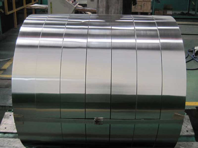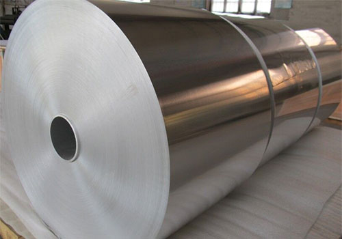
Automotive electrical architectures are expanding rapidly-more sensors, higher data rates, electrified drivetrains, and tighter packaging routes. As harness complexity increases, the cable shield must do more than "cover" a conductor: it must resist heat, vibration, chemicals, and corrosion while delivering stable electromagnetic interference (EMI) performance over the vehicle's lifetime. Plain and laminated cable aluminum foil rolls are purpose-built shielding materials used in automotive wiring systems to provide EMI/RFI attenuation, electrostatic discharge paths, and environmental protection, all in a light and cost-effective format.
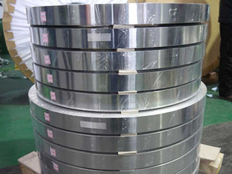
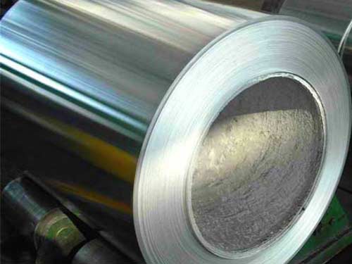
Cable aluminum foil roll is supplied as a slit roll (often narrow widths) designed to be wrapped helically or longitudinally around cable cores. It may be:
- Plain aluminum foil (bare Al): optimized for conductivity and compactness.
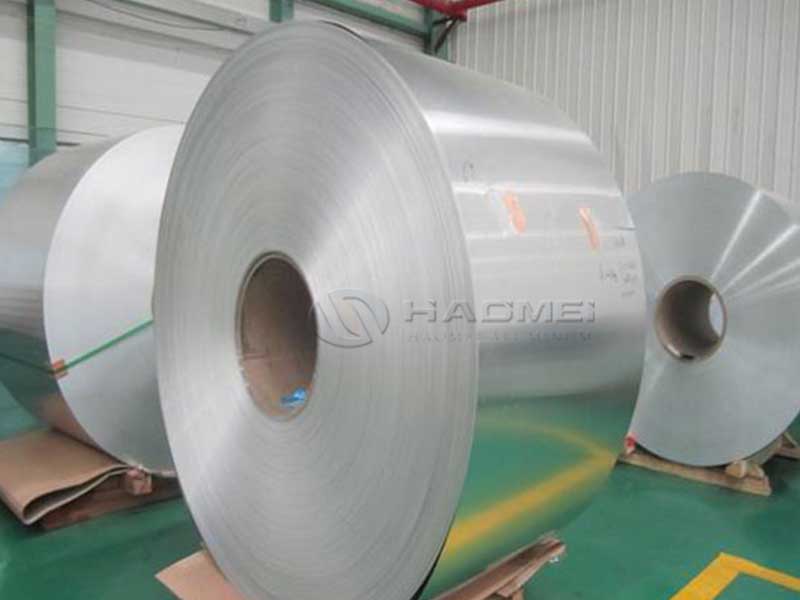
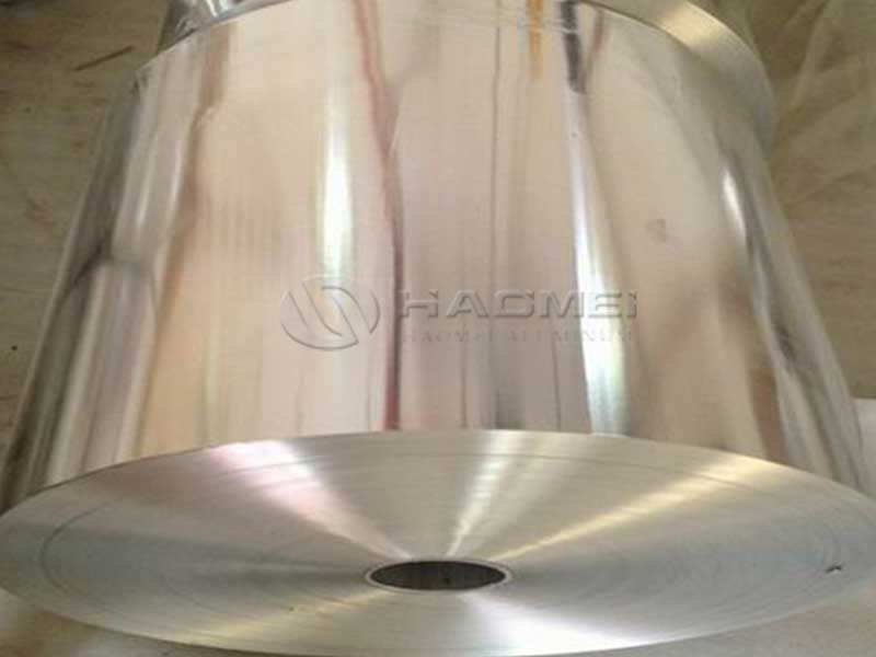
- Laminated aluminum foil: aluminum bonded to PET film (Al/PET) or combined with additional layers (e.g., adhesive, nonwoven, or scrim) to improve tensile strength, dielectric behavior, and processing robustness.
Most automotive shielding uses a foil + drain wire (to ensure a reliable ground connection), and may be paired with braid shielding for higher coverage or lower transfer impedance.
2) Features (What Customers Notice in Production)
EMI Shielding and Signal Integrity Support
Aluminum's electrical conductivity enables the foil to form a continuous barrier that reduces capacitive and radiated coupling between circuits-critical for CAN/LIN, Ethernet, sensor leads, and high-voltage control cables.
Lightweight Protection
Compared with heavier copper braids, aluminum foil provides high shielding performance per unit mass, helping automakers meet aggressive weight targets.
High-Speed Wrap Compatibility
Laminated constructions resist tearing and pinholing during high-speed wrapping, and improve dimensional stability during downstream extrusion/jacketing.
Thermal and Chemical Resilience (Automotive Environment)
Properly specified foil and lamination adhesives withstand engine-compartment temperatures, road splash, oils, and common automotive fluids, helping maintain shield continuity.
3) Typical Constructions and Selection Guide
| Construction | Typical Layer Stack | Strength & Handling | Shielding Effectiveness | Best Use Cases |
|---|---|---|---|---|
| Plain foil | Al only | Moderate; prone to tearing at low thickness | Excellent conductivity; depends on wrap overlap | Cost-sensitive harnesses, short runs, controlled assembly conditions |
| Al/PET laminated foil | Al + PET (polyester) | High; strong tear resistance | Very good; stable coverage and geometry | High-speed production, tight bend radius, long harness runs |
| Al/PET + adhesive (optional) | Al + PET + bonding adhesive | Enhanced wrap integrity | Stable, reduced flutter/noise | High-vibration zones, complex routing |
| Foil + drain wire system | Foil (plain or laminated) + tinned copper drain wire | Best ground termination | High, consistent | Data cables, sensor cables, EMC-critical circuits |
Practical note: For automotive harnesses, Al/PET laminated foil is often preferred because it is far more forgiving during wrapping and maintains integrity after repeated flexing.
4) Chemical Composition (Aluminum Foil Alloy Options)
Automotive cable foil commonly uses 1xxx (commercially pure) aluminum for maximum conductivity, or 8xxx series for improved strength at thin gauges.
| Alloy (Typical) | Al (min %) | Fe (%) | Si (%) | Cu (%) | Mn (%) | Mg (%) | Notes |
|---|---|---|---|---|---|---|---|
| 1235 | 99.35 | ≤0.65 (Fe+Si) | - | ≤0.05 | ≤0.05 | ≤0.05 | Very high conductivity, widely used in foil |
| 8011 | ~98.5 | 0.6–1.0 | 0.5–0.9 | ≤0.10 | ≤0.20 | ≤0.05 | Higher strength, good formability for thin foil |
| 8079 | ≥99.0 | 0.7 max | 0.4 max | 0.05 max | 0.05 max | 0.05 max | Common for high-quality foil, good barrier properties |
Exact limits depend on the governing standard and mill practice; compositions can be customized to customer requirements and compliance targets.
5) Technical Specifications (Typical Supply Range)
The following ranges cover most automotive cable shielding programs. Final values should be confirmed per drawing and validation plan.
| Parameter | Plain Aluminum Foil | Laminated Al/PET Foil | Typical Tolerance / Notes |
|---|---|---|---|
| Aluminum thickness | 7–30 µm | 7–25 µm | Thinner improves flexibility; thicker improves robustness |
| PET thickness | - | 8–25 µm | Common: 12 µm PET for balance of stiffness and wrap |
| Total thickness | 7–30 µm | 20–50 µm | Depends on lamination structure |
| Temper | O / H18 (common) | O / H18 (Al layer) | H18 offers higher strength, less elongation |
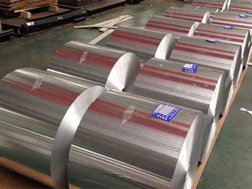
| Width | 5–600 mm (slit) | 5–600 mm (slit) | Narrow widths typical for cable wrap |
| Core ID | 76 mm / 152 mm | 76 mm / 152 mm | Per packaging and line setup |
| Surface finish | Bright / matte | PET side + Al side | PET side often outward for insulation and handling |
| Jointing | Butt / overlap (mill splice) | Butt / overlap | Splice frequency affects line efficiency |
| Pinholes | Controlled | Lower risk due to PET support | Defined by QA plan and inspection method |
6) Performance Metrics (What Matters in the Vehicle)
| Property | Why It Matters | Typical Target/Behavior |
|---|---|---|
| Electrical conductivity (Al layer) | Determines shielding current paths and termination quality | Higher with 1xxx alloys; adequate for foil shields with drain wire |
| Shield coverage & overlap | Influences EMI attenuation consistency | Designed wrap overlap (e.g., 15–25%) for continuity |
| Tear resistance | Prevents line stoppage and shield discontinuity | Laminated foil significantly improves tear performance |
| Flex fatigue resistance | Maintains shielding through bends and vibration | PET lamination improves endurance under repeated flex |
| Thermal stability | Prevents shrink/warp under heat | Lamination adhesive and PET grade must match temperature class |
| Corrosion resistance | Protects against galvanic and environmental corrosion | Proper grounding, jacket design, and material pairing are key |
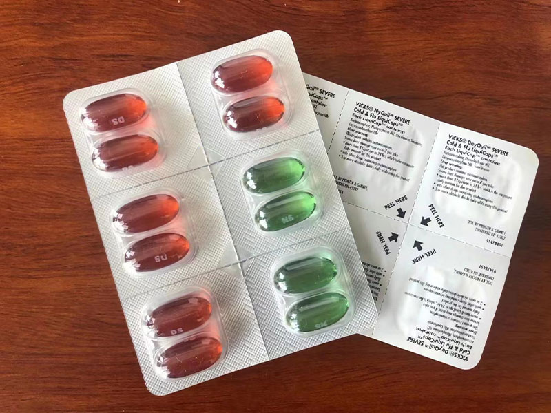
7) Applications in Automotive Wiring Systems
A) Data and Communication Cables
- Automotive Ethernet (100BASE-T1 / 1000BASE-T1): foil shields help manage emissions and susceptibility in dense harness routes.
- CAN / LIN / FlexRay: stabilizes signal integrity when routed near power lines or in noisy environments.
B) Sensor and Low-Level Signal Leads
Wheel speed sensors, camera and radar sub-harnesses, knock sensors, and analog measurement lines benefit from foil shields due to their sensitivity to coupled noise.
C) Hybrid/EV Auxiliary Cables (Non-HV Power)
While high-voltage cables often use more complex shielding systems, many auxiliary circuits in EVs still require robust EMC control-especially around inverters, DC/DC converters, and onboard chargers.
D) Harness Zones with High Exposure
Engine bay, underbody, and near-wheel areas demand shielding materials that maintain integrity despite thermal cycling, abrasion risk, and fluid exposure-laminated foil is typically favored here.
8) Benefits to Customers (Engineering + Purchasing + Manufacturing)
| Stakeholder | Value Delivered | How the Foil Roll Helps |
|---|---|---|
| EMC engineer | Reduced emissions and improved immunity | Continuous conductive barrier + reliable termination options |
| Harness designer | Packaging efficiency | Thin shield layer vs. bulky braid-only solutions |
| Manufacturing | Line stability, fewer defects | Laminated foil reduces tearing, improves wrap consistency |
| Purchasing | Competitive cost/performance | High shielding efficiency at lower mass and material cost |
| Quality & warranty | Durability in vehicle life | Better flex endurance and barrier consistency with lamination |
9) How to Specify the Right Product (Quick Checklist)
- Shield type: plain Al or Al/PET (recommend Al/PET for high-speed wrap and durability).
- Al thickness: choose based on robustness vs. flexibility (common automotive range: 9–20 µm).
- PET thickness & side orientation: PET outward improves handling and insulation; Al inward improves contact to drain wire/core.
- Wrap method: helical vs. longitudinal, overlap requirement, and minimum bend radius.
- Termination strategy: drain wire size, grounding scheme, connector compatibility, and corrosion considerations.
- Validation needs: thermal aging, vibration/flex, salt spray (system-level), and EMI performance testing.