Modern electronics are shrinking while power density keeps climbing. That combination makes thermal management a design-critical function rather than a supporting detail. Slit aluminum fin strip is a purpose-built material form that helps heat sinks move heat away faster, more consistently, and with better manufacturability-especially in high-volume electronics where repeatable fin geometry and clean joining are essential.
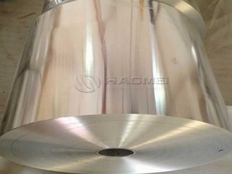
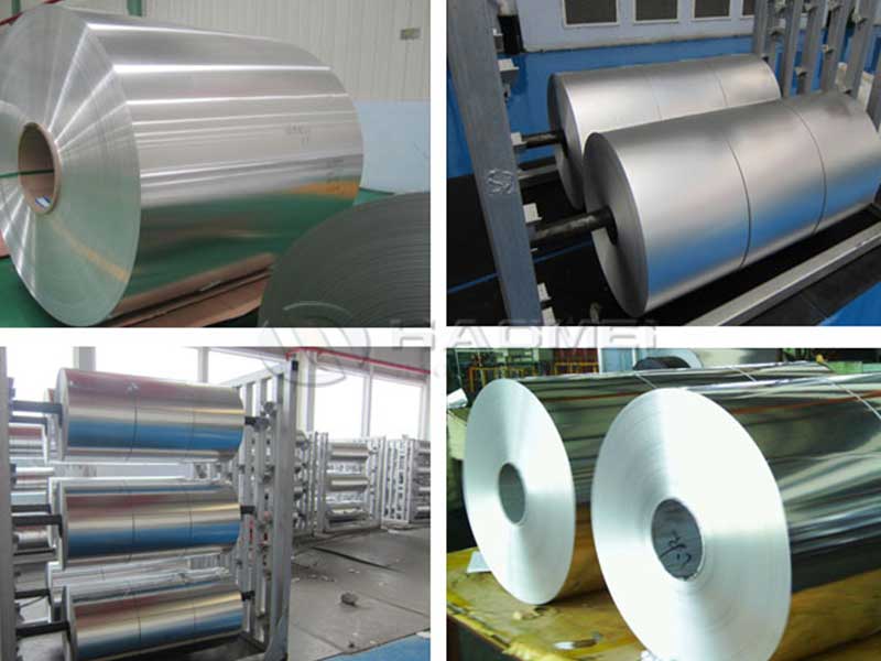
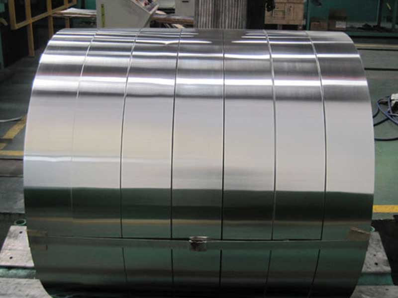
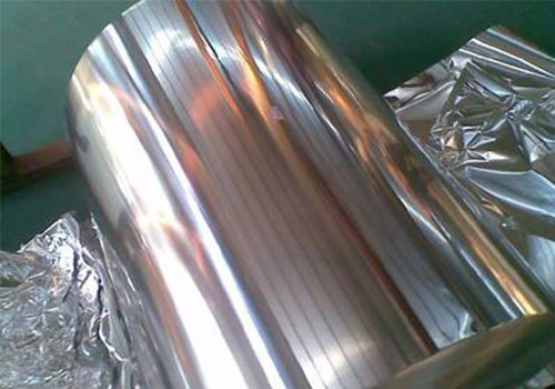
Slit aluminum fin strip is a thin-gauge aluminum strip cut to precise widths (slit), supplied in coil form, and engineered to be formed into fins for heat sinks and heat exchangers. It is commonly used for:
- Skived, folded, louvered, or corrugated fin structures
- Bonded fin stacks on extruded or machined bases
- Lightweight, high-surface-area heat dissipation components
Because the strip is produced and slit under tight control, it supports stable fin pitch, consistent airflow channels, and predictable thermal behavior-factors in achieving high cooling performance across production runs.
Why Slit Fin Strip Improves Heat Sink Efficiency
Heat sink performance is not only about metal conductivity; it is also about geometry, surface area, and manufacturability. Slit fin strip contributes directly to efficiency through several mechanisms.
High Surface Area per Unit Mass
Thin strip enables dense fin packing and tall fin profiles without excessive weight. More effective surface area increases convective heat transfer, especially when paired with forced airflow from fans or blowers.
Stable Fin Geometry for Repeatable Airflow
When fin pitch and fin thickness vary, airflow can become uneven, leading to hot spots. Controlled strip thickness and width reduce variation in forming, supporting predictable pressure drop and improved system-level cooling.
Strong Compatibility with Joining Processes
Depending on alloy and temper, slit fin strip can be tailored for brazing, soldering, adhesive bonding, or mechanical assembly. For electronics, this flexibility simplifies integration with base plates, vapor chambers, or cold plates.
Corrosion-Resistant Options for Harsh Environments
Electronics deployed in telecom shelters, marine settings, or industrial automation benefit from aluminum grades that resist corrosion and accept surface treatments like conversion coating or anodizing (process-dependent and alloy-dependent).
Recommended Alloys and Chemical Composition
Selection typically balances thermal conductivity, formability, strength, and corrosion resistance. The table below lists common alloy families used for fin strip. Exact composition limits may vary by standard and supplier route; the values shown are representative of widely used ranges.
Typical Chemical Composition (wt.%)
| Alloy (Typical) | Si | Fe | Cu | Mn | Mg | Zn | Ti | Al |
|---|---|---|---|---|---|---|---|---|
| 1050 / 1060 (High-purity series) | ≤0.25 | ≤0.40 | ≤0.05 | ≤0.05 | ≤0.05 | ≤0.05 | ≤0.03 | Balance |
| 1100 (Commercially pure) | ≤0.95 (Si+Fe) | included | 0.05–0.20 | ≤0.05 | ≤0.05 | ≤0.10 | ≤0.05 | Balance |
| 3003 (Mn alloy for formability) | ≤0.60 | ≤0.70 | 0.05–0.20 | 1.0–1.5 | ≤0.10 | ≤0.10 | ≤0.05 | Balance |
| 3102 / 3005 (Fin & heat exchange strip variants) | ≤0.70 | ≤0.80 | ≤0.30 | 0.8–1.5 | 0.2–0.8 | ≤0.25 | ≤0.10 | Balance |
| 6063 (when higher strength is needed) | 0.20–0.60 | ≤0.35 | ≤0.10 | ≤0.10 | 0.45–0.90 | ≤0.10 | ≤0.10 | Balance |
Practical guidance
- 1xxx series favors maximum conductivity and excellent forming; ideal for lightweight, high-fin-count designs.
- 3xxx series provides superior formability and robustness during fin forming, with strong corrosion resistance.
- 6xxx series is less common for ultra-thin fin strip but can be selected when added strength and dent resistance matter.
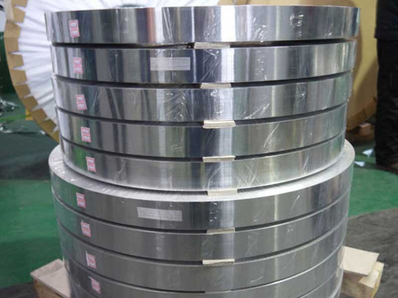
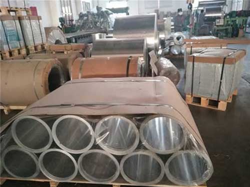
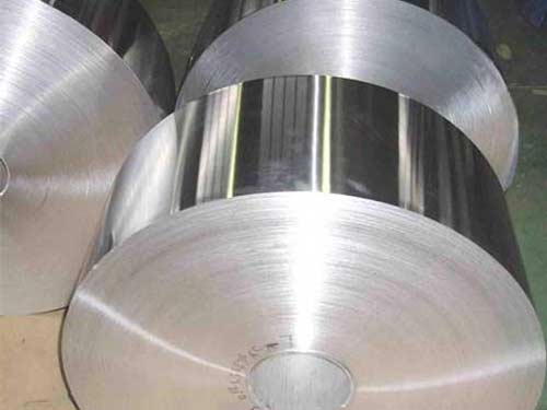
Technical Specifications (Slitting, Geometry, Coil Supply)
Slit fin strip is often specified by thickness, width, coil ID/OD, and edge quality requirements. The following values are typical supply capabilities for electronics thermal products.
Standard Technical Specifications
| Parameter | Typical Range / Option |
|---|---|
| Thickness | 0.05–0.30 mm (common), up to 0.50 mm (application-dependent) |
| Slit width | 6–200 mm (tight tolerance available on request) |
| Temper | O / H14 / H16 / H18 (alloy-dependent); custom intermediate tempers for forming |
| Coil ID | 150 / 300 / 400 / 500 mm (per handling line) |
| Coil OD | up to ~1200 mm (depends on thickness and weight limits) |
| Coil weight | ~50–2000 kg (line and logistics dependent) |
| Edge condition | Deburred / controlled edge; low-burr slitting for fin stamping and folding |
| Flatness | Controlled for stable feeding and forming; camber limits per agreement |
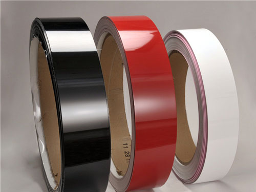
| Surface finish | Mill finish; optional degreased/cleaned; optional coated/pre-treated (process-dependent) |
| Packaging | Moisture barrier + corner protection + vertical/horizontal coil options |
Edge quality matters in fin strip. A clean slit edge reduces micro-cracks during aggressive forming, improves brazing cleanliness, and helps prevent particulate contamination inside electronics enclosures.
Thermal and Mechanical Performance (Typical Data)
While final heat sink performance depends on fin design and airflow, material properties still set the baseline. Values below are typical references for common fin strip alloys and tempers.
Typical Material Property Ranges
| Property | 1xxx Series (e.g., 1050/1060) | 3xxx Series (e.g., 3003/3102) |
|---|---|---|
| Thermal conductivity (W/m·K) | ~200–235 | ~160–200 |
| Electrical conductivity (%IACS) | ~55–62 | ~35–50 |
| Density (g/cm³) | ~2.70 | ~2.73 |
| Tensile strength (MPa, temper-dependent) | ~60–120 | ~110–190 |
| Elongation (%) | high (forming-friendly) | high to medium (excellent forming) |
| Corrosion resistance | excellent | excellent |
Design takeaway
- Choose higher conductivity when heat spreading into fins is the constraint.
- Choose higher strength/form stability when fin geometry must remain rigid at thin gauges and tight pitch.
Features Customers Notice in Production
Consistent Feeding and Forming
Uniform thickness and controlled flatness help coil-fed lines run at higher uptime. Stable strip behavior reduces fin pitch drift, tool wear, and scrap during stamping or folding.
Clean Surface for Joining and Coating
Electronics heat sinks often require bonding to bases, applying thermal interface materials, or receiving conversion coatings. A controlled surface condition helps reduce rejected assemblies and improves coating uniformity.
Precision Slitting for Compact Electronics
Smaller devices demand tighter packaging of thermal hardware. Accurate slit widths support narrow fin modules used in laptop heat sinks, server VRM coolers, and power supply assemblies.
Lightweight with High Strength-to-Performance Ratio
Aluminum fin strip delivers a highly competitive thermal-to-mass efficiency. That helps in portable devices and airborne or vehicle electronics where every gram matters.
Typical Applications in Electronics
Slit aluminum fin strip is used across a broad set of thermal architectures, from passive convection heat sinks to forced-air fin stacks.
Common Use Cases
| Application Area | Typical Components Using Fin Strip | Performance Goal |
|---|---|---|
| Data centers & servers | CPU/GPU fin stacks, VRM coolers, memory airflow fins | sustained high heat flux, predictable airflow |
| Power electronics | IGBT/SiC module heat sinks, rectifiers, inverters | reliable cooling under cycling loads |
| Telecom equipment | base station RF heat sinks, outdoor enclosures | corrosion resistance + long-life thermal stability |
| Consumer electronics | notebook fin modules, gaming consoles, adapters | compactness + low weight |
| LED lighting | finned housings, passive heat sinks | passive convection and durability |
| Industrial automation | drives, PLC thermal plates with fin arrays | stable performance in dust/temperature extremes |
Ordering Notes: What to Specify for Best Results
Clear specifications reduce iteration and accelerate qualification, especially when fin forming is sensitive.
Quick Specification Checklist (Non-exhaustive)
| Item | Suggested Detail |
|---|---|
| Alloy and temper | target forming method and stiffness requirements |
| Thickness and width | include tolerances if fin pitch is tight |
| Edge quality | low-burr requirement; max burr height if critical |
| Surface condition | mill finish vs cleaned; oil level limits for brazing |
| Coil direction | winding orientation for feeding line |
| Packaging | moisture protection; anti-scuff for cosmetic parts |
| Compliance | RoHS/REACH documentation if needed |
Slit aluminum fin strip is a high-impact material choice for electronics heat sinks because it combines thin-gauge efficiency, precision geometry, and manufacturing repeatability. With the right alloy and temper selection-often from the 1xxx and 3xxx families-customers gain excellent formability, strong corrosion resistance, and dependable thermal performance. Whether the target is a compact laptop module, a high-power inverter, or a server-class fin stack, slit fin strip offers an efficient path to higher surface area, smoother airflow, and consistent production quality.