Broadband networks move enormous volumes of data through coaxial and hybrid cable architectures where shielding quality is often the difference between stable throughput and intermittent noise-driven failures. High Conductivity Cable Foil is an engineered aluminum foil product designed specifically for data transmission cable shielding-delivering low resistance, consistent EMI/RFI attenuation, and robust mechanical reliability during high-speed cable manufacturing.
What the Product Is
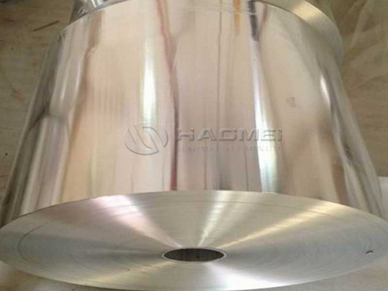
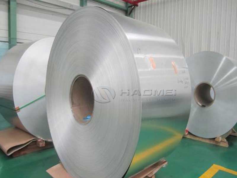
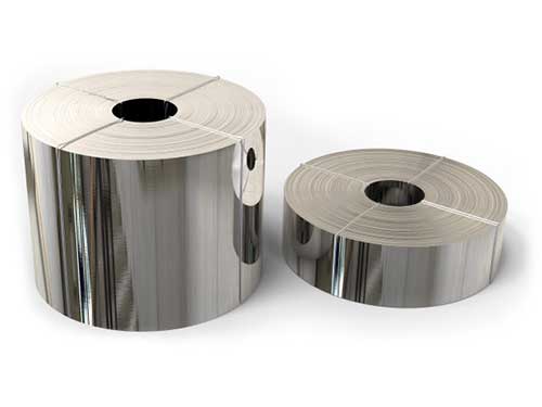
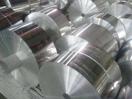
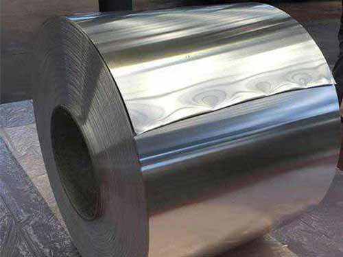
High Conductivity Cable Foil is a thin, precisely rolled aluminum foil-typically single-side or dual-side laminated (e.g., with PET or PE) or used as bare foil depending on the cable architecture. It is intended for:
- Broadband coaxial cables
- Drop cables and trunk cables
- LAN/data cables with foil shields
- Hybrid power + data constructions
- Low-voltage signal and communication cables requiring high shielding performance
The product is optimized for both electrical performance (conductivity, continuity, shielding) and manufacturability (stable elongation, flatness, controlled pinholes, consistent thickness).
Why Conductivity and Foil Quality Matter in Broadband Cables
In high-frequency data transmission, shielding must provide:
- Low transfer impedance to minimize coupled noise
- Consistent circumferential coverage to prevent leakage paths
- Stable contact and bonding to maintain continuity over bending and thermal cycling
High conductivity aluminum improves the shield's current-carrying capability for induced currents and helps reduce resistive loss along shield pathways. Equally important are foil integrity (low pinholes), surface cleanliness, and uniform mechanical properties, which collectively reduce the likelihood of micro-gaps, delamination, and intermittent shielding discontinuities during service.
Features (Designed for Signal Integrity)
1) High Electrical Conductivity for Reliable Shield Performance
By controlling alloy purity and limiting resistivity-increasing elements, the foil supports strong electrical continuity-especially important in longitudinal shield configurations and laminated shields where bond quality and surface condition influence effective performance.
2) Excellent Shielding Consistency via Tight Gauge Control
Uniform thickness reduces impedance variation and helps maintain stable shielding performance along the cable length-critical for broadband systems where minor defects can manifest as localized noise ingress.
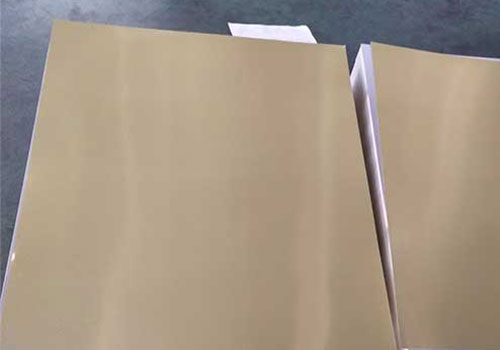
3) Clean, Lamination-Ready Surface
Surface quality is tuned for:
- Stable adhesive wetting (for PET/PE laminations)
- Reduced risk of delamination
- Predictable forming around dielectric cores
4) Robust Mechanical Balance for High-Speed Cable Wrapping
Engineered temper and controlled elongation enable:
- High-speed longitudinal wrapping
- Reduced cracking at overlap seams
- Controlled springback and improved forming
5) Low Pinhole / Defect Strategy
Pinhole control supports improved insulation integrity and reduces local weak points that can compromise shield uniformity-particularly important when foil is also part of moisture barrier or bonding stack-ups.
Typical Alloy and Chemical Composition (Reference)
High conductivity cable foil is commonly produced using 1xxx-series aluminum (high purity) or conductivity-optimized compositions. Below is a representative composition window used in high-conductivity foil-grade aluminum.
Note: Actual targets can be tailored to customer process needs (lamination, bonding, bending radius, and shielding design).
Chemical Composition (wt. %)
| Element | Typical Range | Function / Notes |
|---|---|---|
| Al | Balance (≥ 99.0%) | Primary conductor; purity supports conductivity |
| Fe | 0.20–0.60 | Controls strength; excessive levels may reduce conductivity and formability |
| Si | 0.05–0.25 | Impurity control; affects conductivity and rolling behavior |
| Cu | ≤ 0.05 | Kept low to maintain high conductivity |
| Mn | ≤ 0.05 | Typically limited; can increase strength but affects conductivity |
| Mg | ≤ 0.05 | Limited to protect conductivity and surface behavior |
| Zn | ≤ 0.05 | Impurity limit |
| Ti | ≤ 0.03 | Grain control in casting; tight control for foil uniformity |
| Others (each) | ≤ 0.03 | Controlled to minimize resistivity impact |
| Others (total) | ≤ 0.10 | - |
Technical Specifications (Typical Supply Ranges)
The following table summarizes typical capability ranges for cable foil used in broadband/data applications. Values are indicative and can be aligned with specific cable designs.
Product Technical Specifications
| Parameter | Typical Range / Options | Why It Matters |
|---|---|---|
| Thickness (foil) | 6–50 µm (common: 9–25 µm) | Impacts shielding, handling, and overlap integrity |
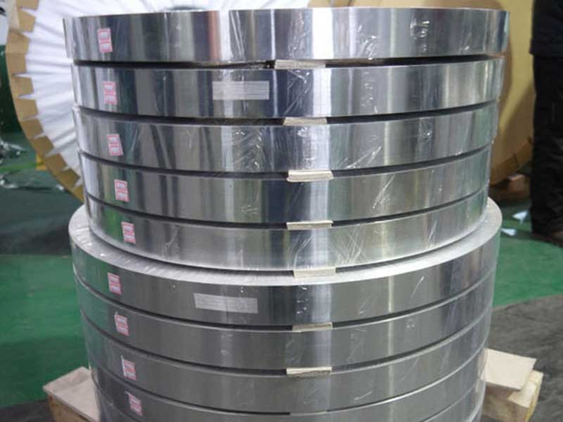
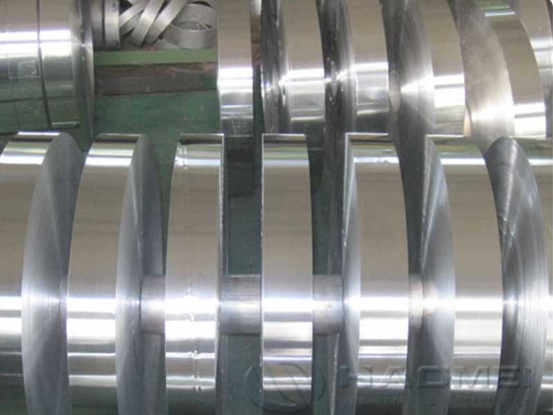
| Width | 10–1300 mm | Covers narrow wrap tapes to wide lamination stock |
| Temper | O / H14 / H16 / customer-defined | Balances formability and strength during wrap |
| Conductivity | ≥ 60% IACS (typ.), up to ~63%+ for high purity | Lower resistive loss and stable shielding currents |
| Electrical resistivity (20°C) | ~2.65–2.90 µΩ·cm (grade dependent) | metric for high-conductivity design |
| Tensile strength | ~70–160 MPa (depending on temper/thickness) | Prevents tearing at high line speeds |
| Elongation | ~1.5–12% (depending on temper/thickness) | Helps avoid cracking at seams and bends |
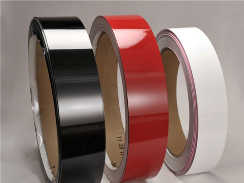
| Surface finish | Bright / matte / one-side treated | Tuned for lamination, bonding, or contact |
| Roughness (Ra) | ~0.2–0.8 µm (process dependent) | Affects adhesion and electrical contact behavior |
| Pinhole control | Customer-specified limits (per area) | Improves consistency and barrier behavior |
| Coil ID | 76 / 152 / 300 mm (common) | Matches laminator and wrapper hardware |
| Packaging | Moisture-protected, edge-protected | Reduces oxidation and handling damage |
Mechanical and Performance Metrics (What Customers See in Production)
Mechanical Properties (Representative)
| Property | Typical Value Band | Impact on Cable Manufacturing |
|---|---|---|
| Yield strength (Rp0.2) | ~30–140 MPa | Controls permanent deformation and seam stability |
| Tensile strength (Rm) | ~70–160 MPa | Reduces web breaks during wrapping/lamination |
| Elongation (A50) | ~1.5–12% | Higher elongation improves bend and overlap tolerance |
| Work hardening stability | High (controlled) | Predictable behavior across long production runs |
Cable-Relevant Performance
| Performance Metric | Practical Benefit | Typical Outcome |
|---|---|---|
| Shield continuity stability | Fewer intermittent shielding faults | Reduced field returns and fewer "hard-to-debug" noise issues |
| Consistent wrap formability | Stable overlap and seam integrity | Less scrap, fewer line stops |
| Lamination bond consistency | Lower delamination risk | More robust handling and long-term durability |
| Defect/pinhole management | Better uniformity and reliability | More consistent shielding and barrier performance |
Use Cases and Applications
1) Broadband Coaxial Cables (Trunk/Feeder/Drop)
Cable foil supports shielding layers that help protect signal integrity against external electromagnetic interference from:
- Power equipment
- Industrial motors
- Radio transmitters
- Dense urban RF environments
Best fit: laminated foil (Al/PET) for stable handling and coverage, or bare foil integrated with braid layers depending on cable design.
2) High-Speed Data Cables (Foil-Shielded Twisted Pair / Hybrid)
For data cables requiring protection from alien crosstalk and ambient EMI, high conductivity foil provides an effective shielding layer with consistent manufacturability at scale.
3) Hybrid Broadband + Power or Control Cables
Where multiple services share a cable structure, foil shielding helps isolate sensitive data paths from switching noise and power transients.
4) Indoor/Outdoor Installations with Thermal Cycling
Stable mechanical properties and controlled lamination performance improve resilience against bending, vibration, and temperature changes that can otherwise degrade shield integrity.
| Customer Need | How High Conductivity Cable Foil Helps |
|---|---|
| Enhanced signal integrity | High conductivity + consistent thickness improves shielding uniformity and continuity |
| Lower noise ingress | Stable wrap and reduced defect pathways help suppress EMI/RFI coupling |
| Higher manufacturing uptime | Balanced temper and tensile behavior reduce breaks and line interruptions |
| Long-term reliability | Strong adhesion compatibility and mechanical stability reduce delamination and seam issues |
| Flexible design integration | Works as bare foil or in laminates (e.g., Al/PET), supporting many cable architectures |
Selection Guidance (Quick Checklist)
Choose your foil configuration based on cable design priorities:
- Need maximum forming tolerance / high-speed wrapping? Consider O temper or softer tempers in thin gauges.
- Need stronger web handling and tighter seam control? Consider H14/H16 with validated elongation targets.
- Need excellent lamination stability? Specify surface treatment, roughness window, and cleanliness requirements.
- Operating in high-noise environments? Prioritize conductivity + gauge uniformity + tight pinhole limits.